What are you looking for?
Oscilloscope
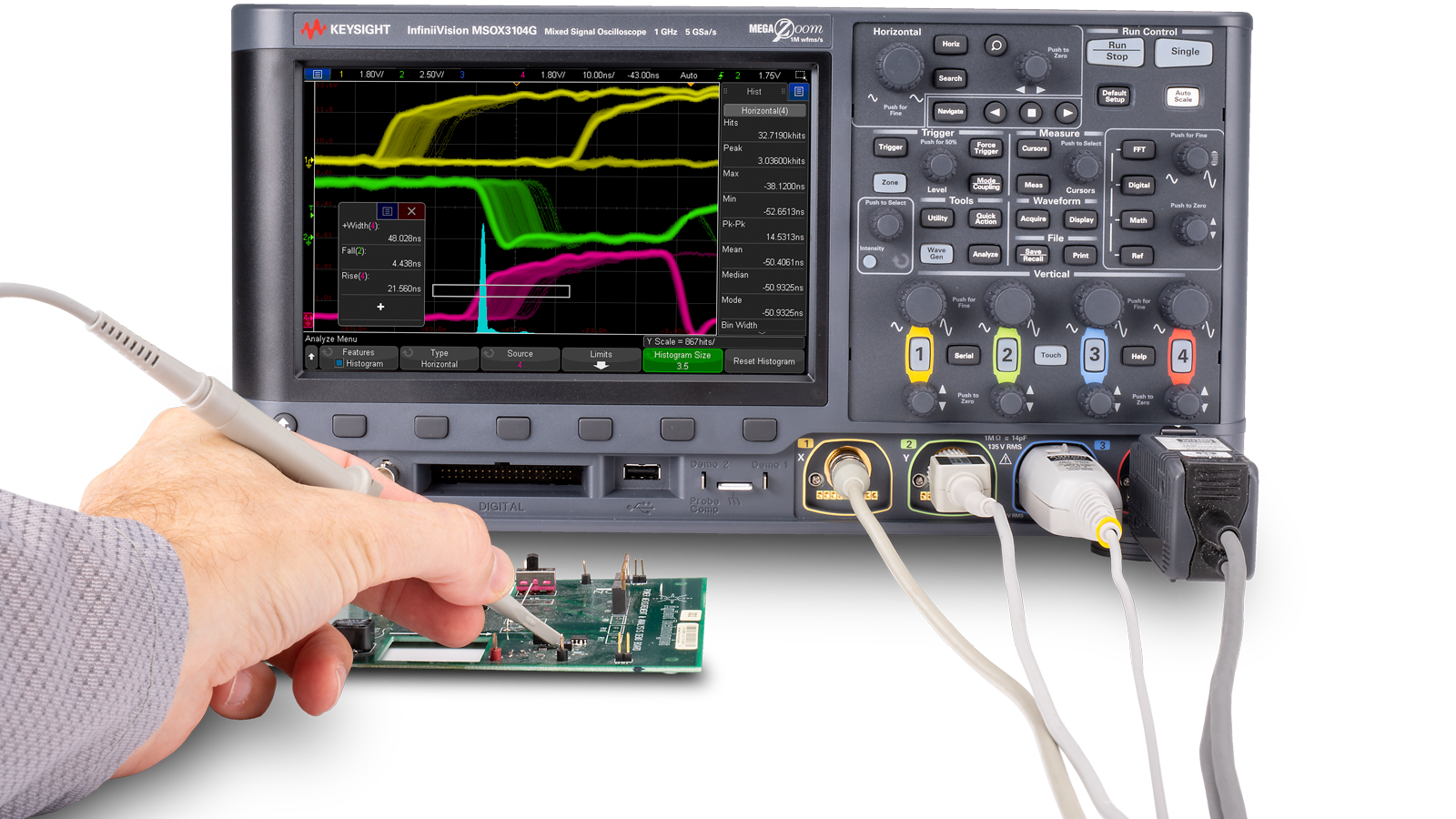
Make better measurements with award-winning Keysight oscilloscopes
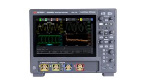
Buy an HD3 and choose your reward
Select two free software applications with your purchase
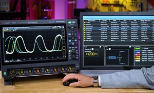
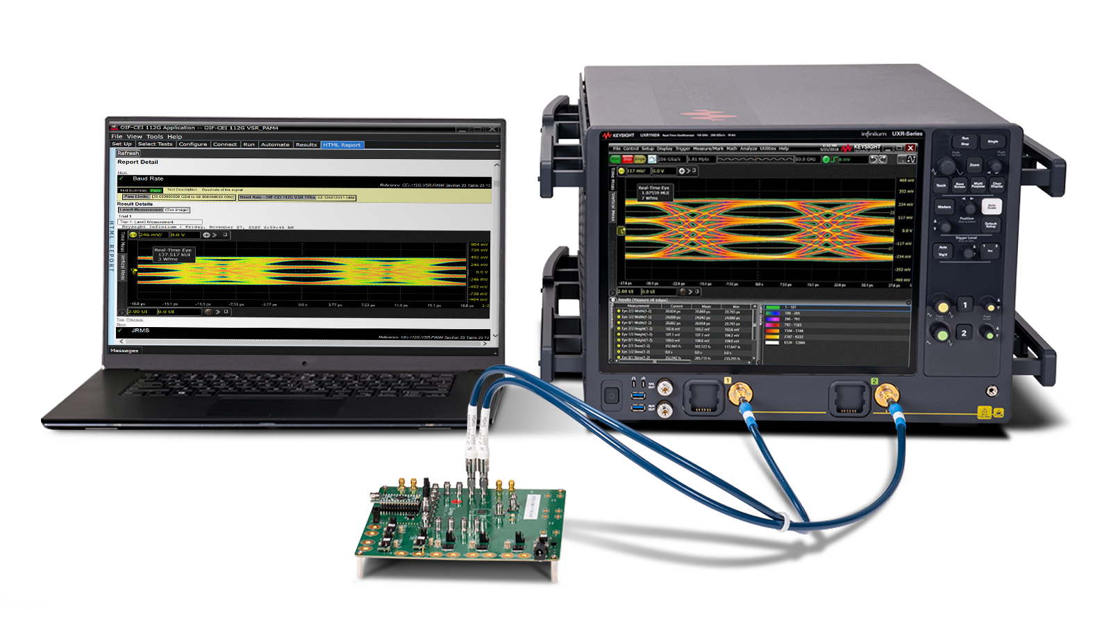
Oscilloscope Test Measurements You Can Count On
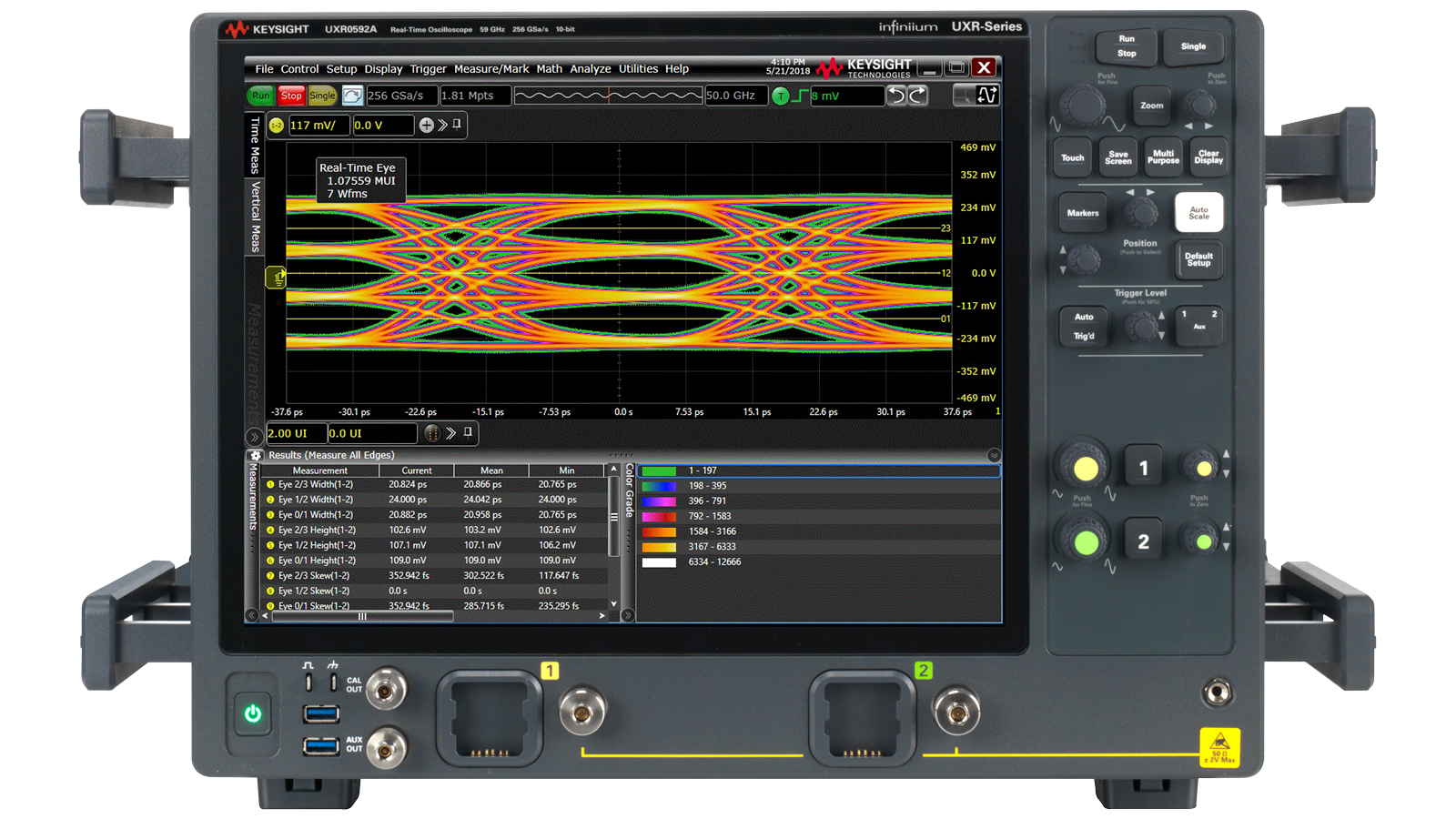
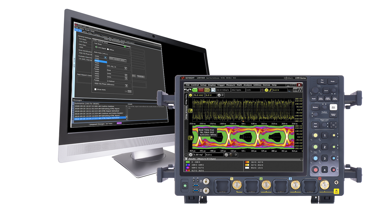
Whether you design, debug, or perform compliance tests, you need proven measurement technology to be successful. Our oscilloscope hardware, with signal integrity, high effective number of bits (ENOB), and the fastest waveform update rates, captures the true performance of your device under test. Couple this with superior protocol decoding, analysis, and compliance software, and you’re guaranteed to get measurements you can trust.
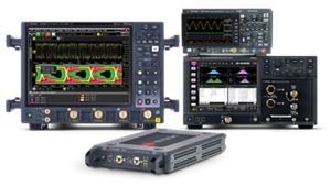
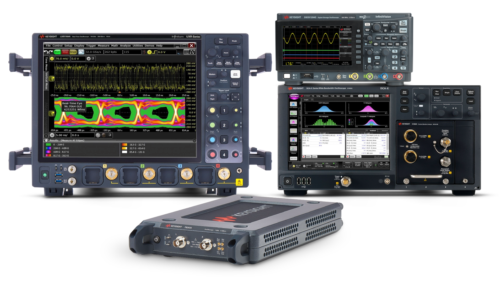
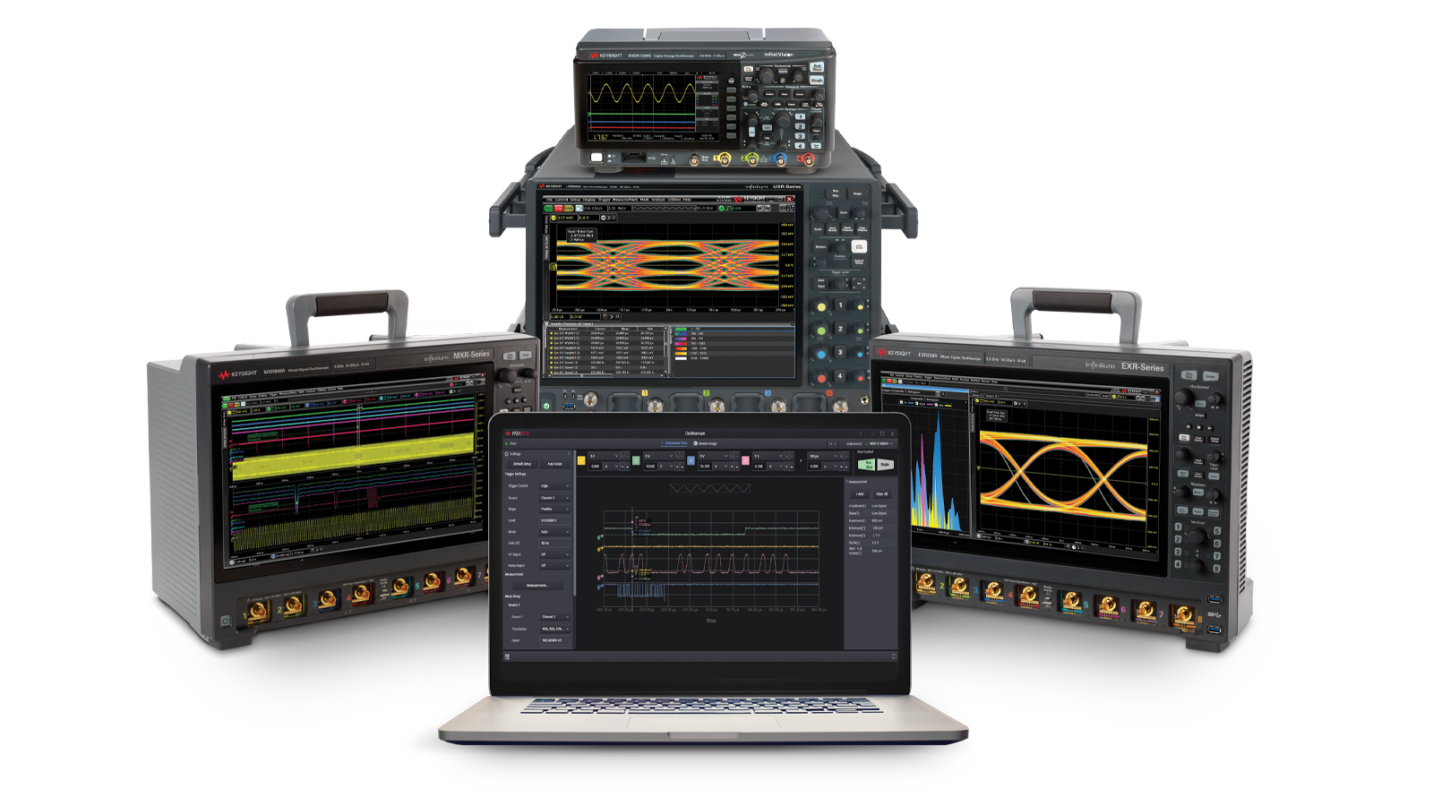
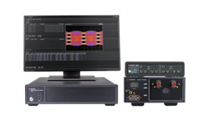
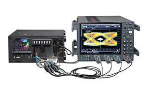
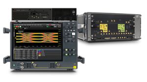
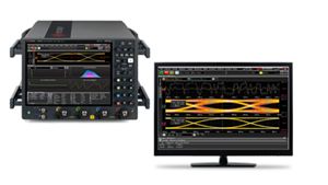
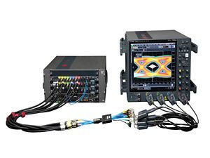
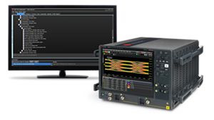
Find the Oscilloscope That's Right For You
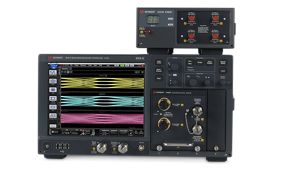
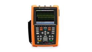
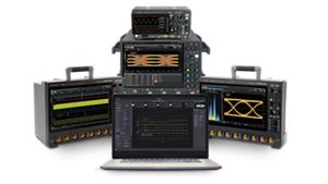
Whether you need high signal integrity, a portable form factor, or an affordable oscilloscope, we've got you covered. With our broad range of oscilloscopes, you are sure to find the right scope no matter where you are in the development cycle.


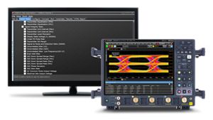
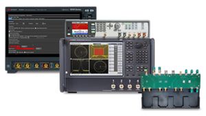
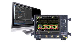
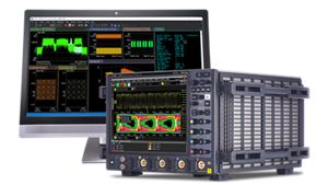
Select the Oscilloscope Software That's Right For You
Keysight offers the industry's largest selection of compliance, debugging, and application-specific oscilloscope test software. Explore and select the oscilloscope software that completes your testing solution.
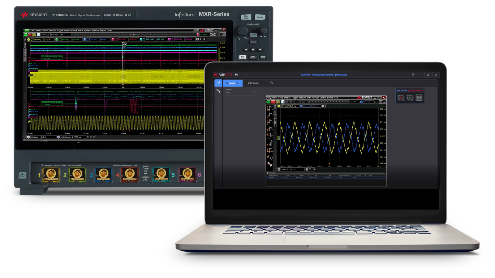
Industry's largest selection of oscilloscope test software
The software works seamlessly with your Keysight oscilloscope and provides the insight you need to quickly and easily innovate your best designs. Explore how you can create, test, and validate your designs faster with automated software testing and stay up to date on the latest standards with over 50 compliance test software packages.


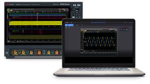
PathWave BenchVue Oscilloscope Software
PathWave BenchVue oscilloscope test software for PCs makes it easy to connect, control, capture, and view measurement data from your oscilloscopes with no additional programming. The software enables you to do the following:
- Connect and control your oscilloscopes in the cloud
- Log data, screenshots, and system status
- Export measurement data in the desired format
- Make prototypes and create automated custom test sequences
- Save and replicate instrument configurations to repeat results
- Visualize multiple types of instrument measurements simultaneously


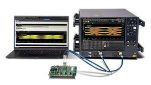
Over 50 Compliance Test Software Packages
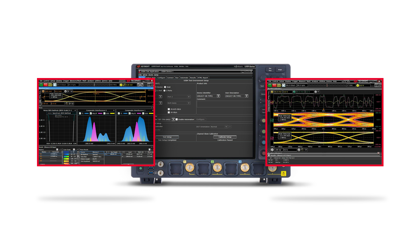
High-speed digital transceivers require validation to ensure compliance with the latest standards. Pair your Keysight oscilloscope with over 50 compliance test software packages to speed up debugging and validation.
- High-speed digital: USB, DDR, MIPI, PCIe, and HDMI
- Automotive: CAN, LIN, FlexRay, and Ethernet
- Aerospace and defense: MIL-STD and ARINC 429
- General-purpose: I2C, SPI, NFC, SATA, SAS, XAUI, and more

New to Oscilloscopes?
Learn the basics and advanced applications to help you develop a deeper understanding of oscilloscopes. Understand the functions of an oscilloscope, signal characteristics, types of waveforms, how an oscilloscope works, types of oscilloscopes, and key specifications to look out for when selecting an oscilloscope.
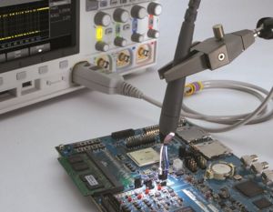
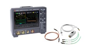
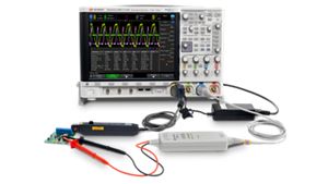
Which Oscilloscope Test Probe Do You Need?
Keysight offers a broad range of voltage, current, and optical probing solutions for InfiniiVision and Infiniium Series oscilloscopes. Check out this guide to see which probe is right for your testing needs.
Understanding common probing mistakes is crucial to making accurate measurements. Probes can introduce loading, noise, and jitter into your system. The electrical behavior of your probes greatly affects your measurement results and potentially even the operation of your device. Learn how to avoid common oscilloscope probing pitfalls in this eBook.

Related Use Cases

How to Optimize 1.6T Optical Transceiver Manufacturing Tests

How to Optimize 800G Optical Transceiver Manufacturing Tests

How to Test USB4 Version 2.0 Transmitter Compliance

How to Test for HDMI Physical Layer Source Compliance

How to Perform Power Integrity Analysis
How to Test for DDR4 Compliance
How to Debug Electronic Devices with High Accuracy
How to Characterize Automotive Serial Buses
How to Measure AC Signals Over DC Signals

How to Evaluate FEC Performance for High-Speed Ethernet Links

How to Analyze PCB Signal Integrity

How to Test for HDMI Physical Layer Sink Compliance

How to Verify Automotive Ethernet Transmitter Compliance
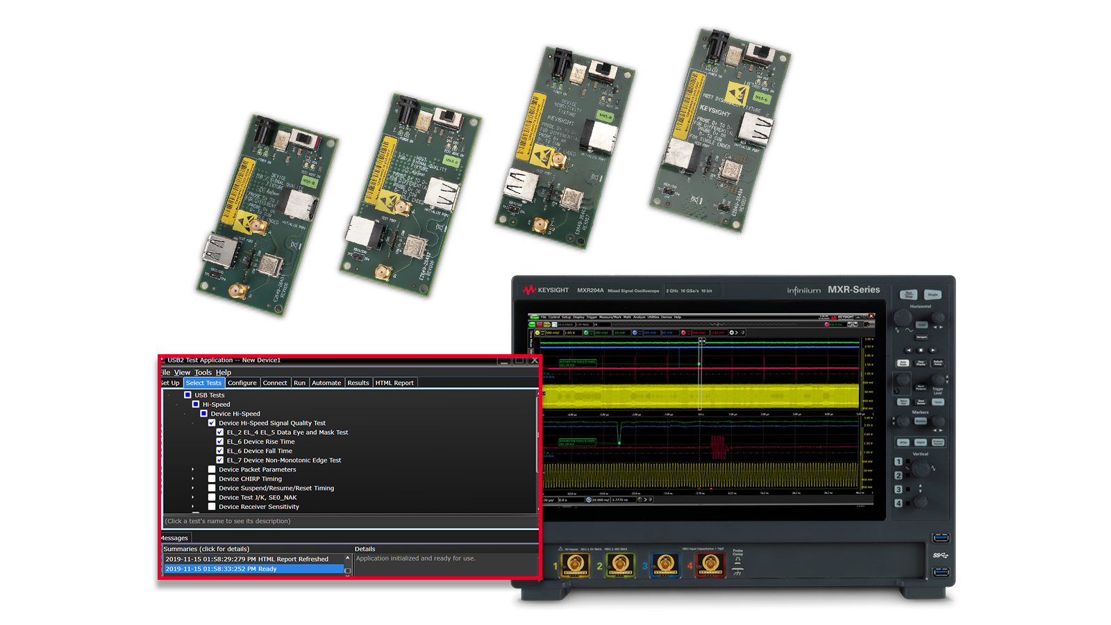
How to Test USB 2.0 Interface Compliance
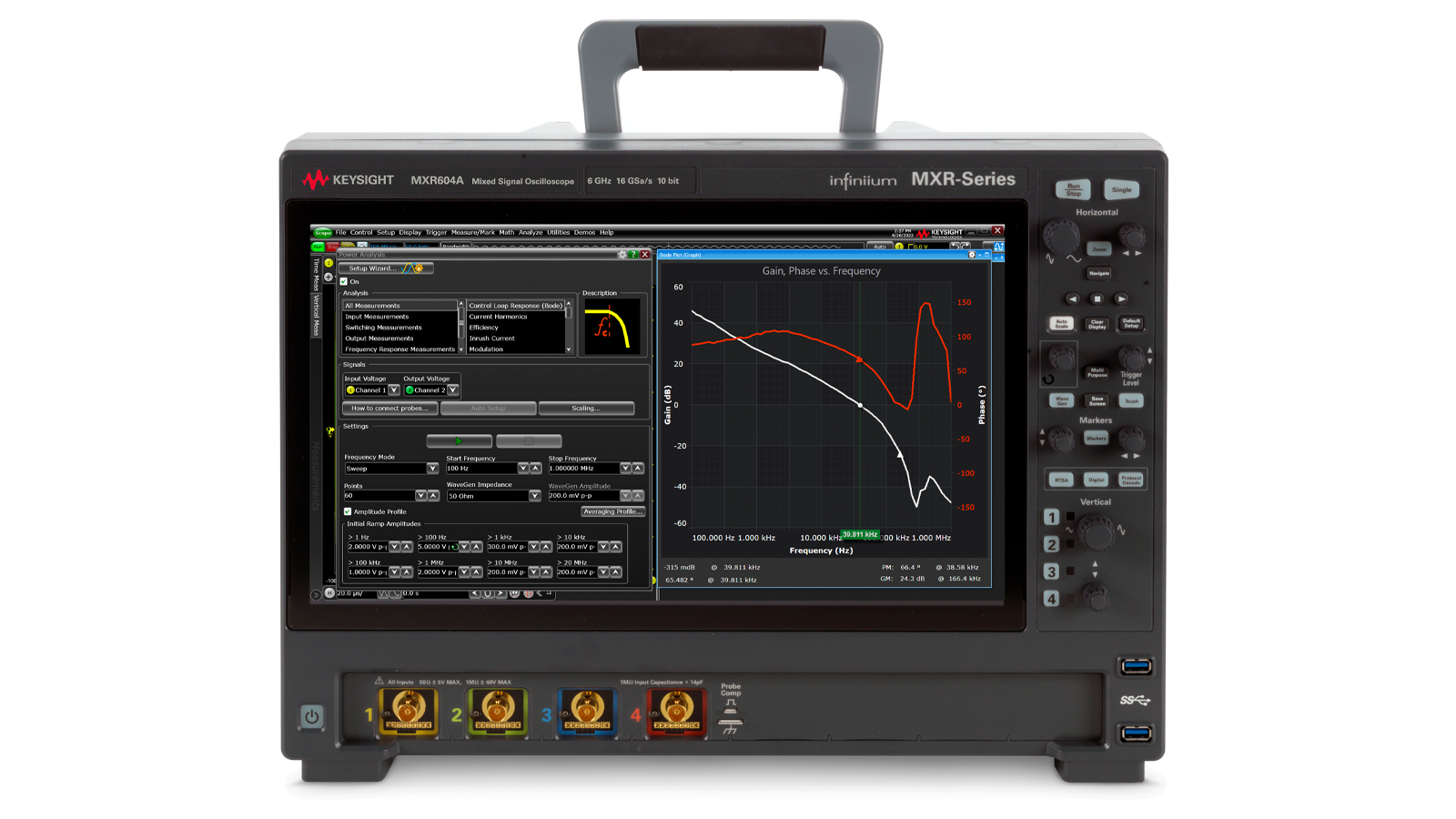
How to Measure Frequency Response (Bode Plot)

How to Test 5G Communication Systems
How to Automate Conformance Debug and Verification
How to Test 400G / 800G Electrical Transmitter Conformance

How to Test USB Type-C Power Delivery

How to Analyze and Debug USB Type-C Links
How to Test DDR5 Transmitter Compliance
How to Test USB4 Transmitter Compliance

How to Test PCIe® 5.0 Transmitter Compliance

How to Test Switch Mode Power Supplies

How to Characterize Embedded Serial Buses

How to Test PCIe® 6.0 Transmitter Compliance

How to Test 5G NR MIMO

How to Test Automotive SerDes Transmit Conformance

How to Accelerate High-Speed Digital Compliance Testing
KeysightAccess
Reduce budget challenges with KeysightAccess subscription service.
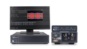
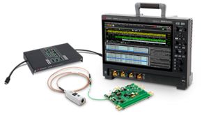
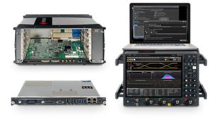
Extend Your Capabilities With The Right Tools
Get more functionality out of your oscilloscope today by pairing it with the right accessories to improve productivity and the right Keysight PathWave design and test automation software to accelerate your product development.


.png)
.png)
Featured Resources


Oscilloscope FAQs
An oscilloscope, sometimes shortened to “scope” or “o-scope”, is a test instrument that captures and displays the behavior of electrical signal over time. For example, it can plot a graph of voltage (y-axis) versus time (x-axis) on its display.
Oscilloscopes are powerful tools that engineers use for designing and testing electronic devices. They are vital in determining which components of a system are behaving correctly and which are malfunctioning. They can also help you determine whether or not a newly designed component behaves the way you intended. This can be done by analyzing signal properties such as amplitude, period, frequency, rise time, pulse width, and more. Modern digital oscilloscopes can also perform mathematical functions on waveforms, such as a Fourier transform, making analysis quicker.
All modern oscilloscopes are digital storage oscilloscopes (DSOs), which use digital signal processing to capture and display the analog signal. If the scope has the ability to accept digital signals, it is a mixed-signal oscilloscope (MSO). If the scope has a spectrum analyzer feature built into it, it is a mixed-domain oscilloscope (MDO), though this terminology is less common.
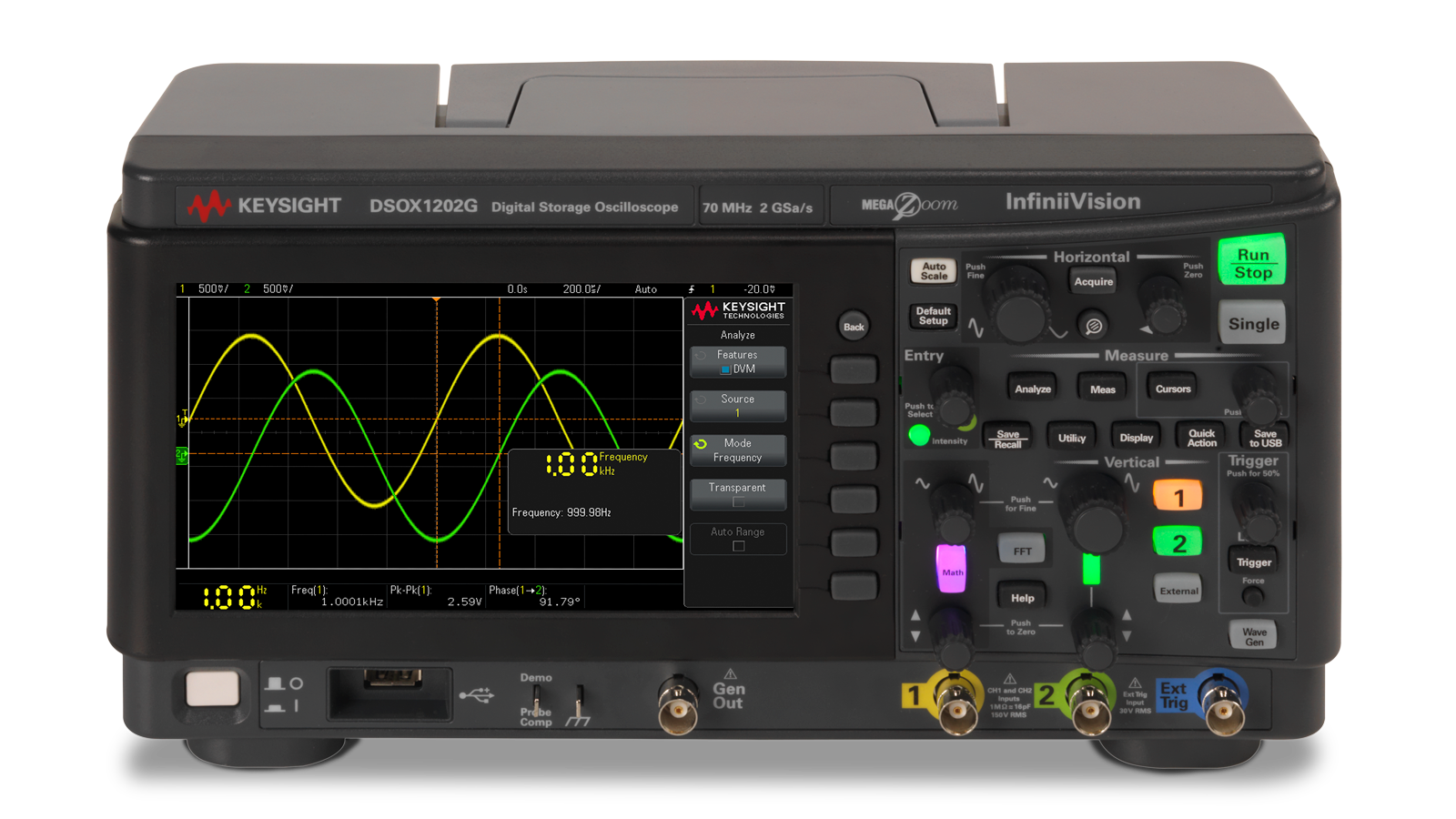
Digital Storage Oscilloscope (DSO)

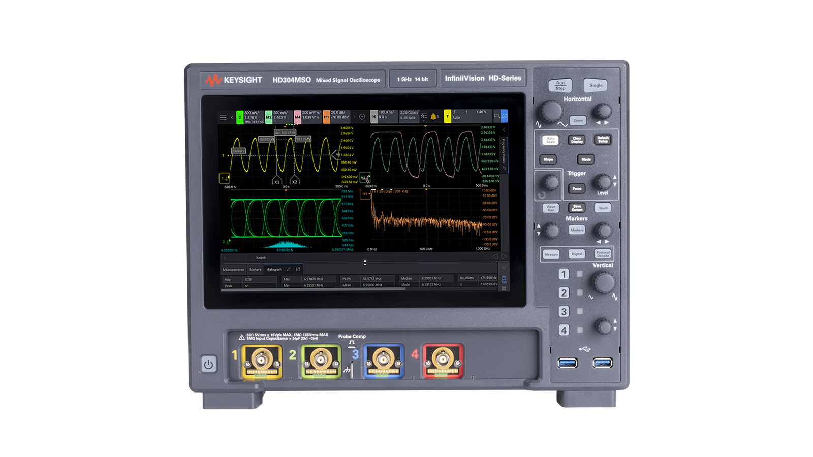
Mixed-Signal Oscilloscope (MSO)
Mixed-Domain Oscilloscope (MDO)
Test engineers and developers use oscilloscopes to display, graph, and analyze electrical signals during research and development, validation, quality assurance, and troubleshooting or debugging of electronic systems, circuit boards, and integrated circuits. Oscilloscopes play a key role across all industries for a variety of applications and technologies, including high-speed digital electronics, optical communication, RF, power electronics, automotive, and aerospace and defense.
An oscilloscope is a critical test instrument for observing, analyzing, or recording the behavior of an electrical signal. Some specific use cases for oscilloscopes in an electronics laboratory include measuring voltage waveforms, analyzing electronic signals, detecting unwanted noise and crosstalk, and evaluating harmful transients in power systems.
An oscilloscope uses a probe to connect to a test point in a circuit and amplifies or attenuates the voltage at that point. The signal path after that depends on the scope, but in general analog circuitry conditions the signal and an analog-to-digital converter digitizes it for further evaluation, processing, and analysis.
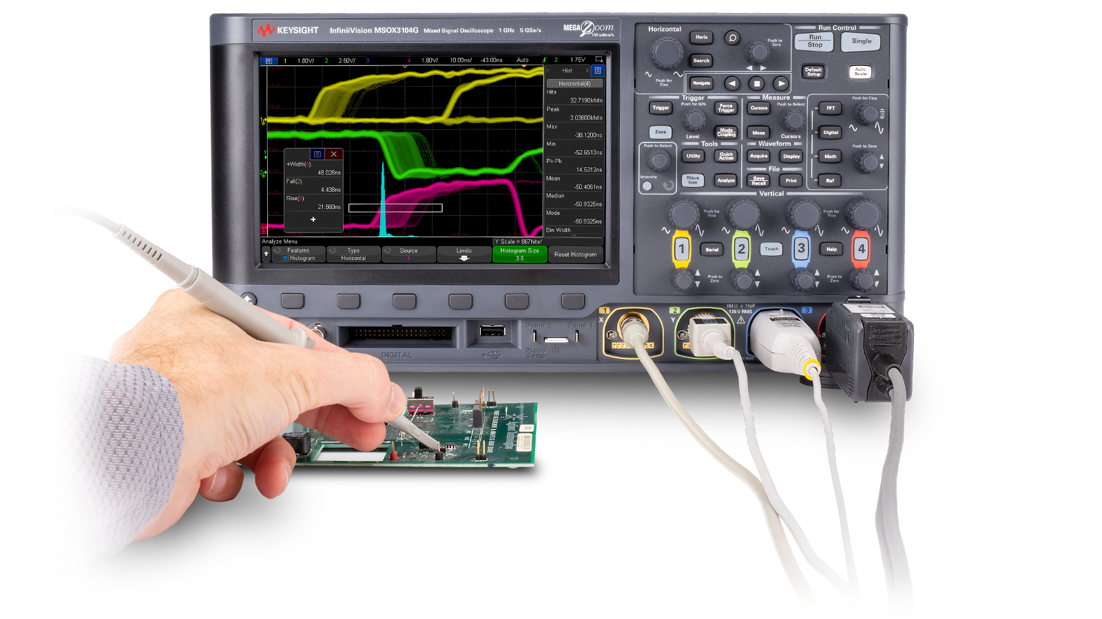
With so many brands and types of oscilloscopes available, they might look different from one another, but most have the same basic steps to get started. Here’s a step-by-step guide on how to use an oscilloscope:
- Connect the Probe: Attach the probe to the oscilloscope's input channel. Make sure it’s securely connected. If you have an attenuated probe, you may need to compensate your probe until you have a perfect square waveform.
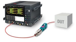
- Probe the DUT: Connect the probe to your device under test (DUT) by attaching the probe tip to the point of interest on the circuit and connecting the ground clip to a common ground point on the DUT.
- Adjust Vertical and Horizontal Scales: Use the oscilloscope controls to adjust the vertical (voltage) and horizontal (time) scales. This ensures that the waveform is displayed correctly on the screen.
- Set the Trigger: Use the trigger setting to stabilize the waveform. The trigger helps ensure that the signal is consistently displayed. Adjust the trigger level and type as needed.
- Interpret the Waveform: Look at the waveform on the screen. The x-axis represents time, and the y-axis represents voltage. Observe the shape, frequency, and amplitude of the signal.
- Analyze the Waveform: Identify any issues or anomalies. Is the signal behaving as expected? Are there noise spikes or irregularities? Troubleshoot any detected problems to ensure accurate signal performance. You may use the oscilloscope's features, like cursors and automated measurements, to assist in your analysis.
More information:
Keysight offers a wide range of free technical resources for engineers to learn about essential oscilloscope functions and how to get started.
- Learn oscilloscope fundamentals with the How to Use an Oscilloscope.
- Get started with Keysight oscilloscopes with free Oscilloscope Technical Resources such as lab guides and tutorials, advanced training guides, and application notes.
An oscilloscope captures and displays a signal in the time domain, while a spectrum analyzer captures and displays a signal in the frequency domain. Sometimes, an oscilloscope will have a spectrum analyzer feature built into it for the convenience of analyzing the signal in the time and frequency domains.
Passive probes: These are the most common types, suitable for low-frequency measurements. They only contain components like resistors and capacitors that passively respond to input signals, so they do not require external probe power.
Active probes: These are used for high-frequency measurements. They require external probe power for the active electronic components in the probe, such as amplifiers and transistors, which are used to improve signal fidelity and performance.
Differential probes: These consist of two sensing leads that measure the differential voltage between two test points where neither lead is grounded.
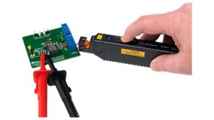
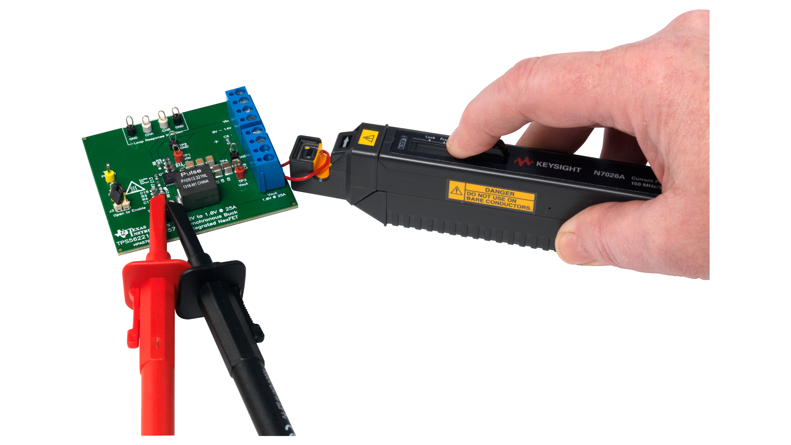
Current probes: These probes measure current waveforms. There are two types: clamp-on versions that do not break the circuit and types that you connect in series with the circuit.
For a complete selection guide on application-specific oscilloscope probes such as Hi-Z+ probes, high-frequency differential probes, power rail probes, and optical probes, you may refer to this Oscilloscope Probes Selection Guide.
Compatibility is not assured, even though many probes and oscilloscopes use standard connectors. It’s critical to verify:
- Bandwidth compatibility: The probe’s bandwidth should match or exceed the oscilloscope’s bandwidth.
- Connector type: Ensure the probe’s connector matches the oscilloscope input.
- Voltage and current ratings: Confirm the probe can handle the oscilloscope’s input range.
It would be best to refer to the specific oscilloscope and probe manuals for detailed operation and maintenance guidelines, which are crucial for effective and accurate measurements.
Automatic triggering, while convenient, may not always provide the level of precision engineers require. In contrast, normal triggering empowers engineers to specify the exact point at which they want to capture a waveform, offering a level of control and accuracy that can be crucial when troubleshooting problems. For instance, if you need to capture a specific pulse, normal triggering allows you to specify the precise time the pulse occurs. When you switch to the Single trigger mode, your oscilloscope will temporarily operate in normal trigger mode to prevent an automatic force trigger.
- In normal mode, the sweep starts only when the trigger settings are met. If the trigger is not met, the screen is not updated. This can be useful when capturing a transient event that may only happen once.
- In auto mode, the sweep is triggered automatically and continuously.
- In single mode, the sweep only occurs when the trigger is activated manually. This can be useful when you want to capture a particular single trigger event or signal condition.
Learn more about the applications and examples of when to use each mode from this deep dive lesson video.


Want help or have questions?