Bit error ratio testers (BERT)

Receiver Characterization And Compliance Testing

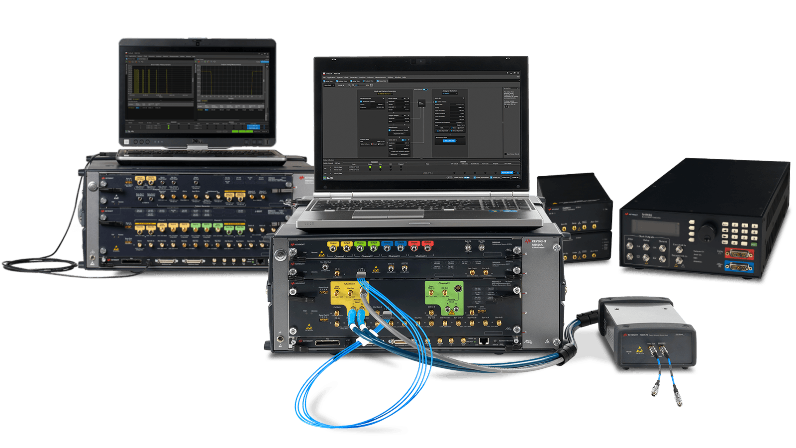
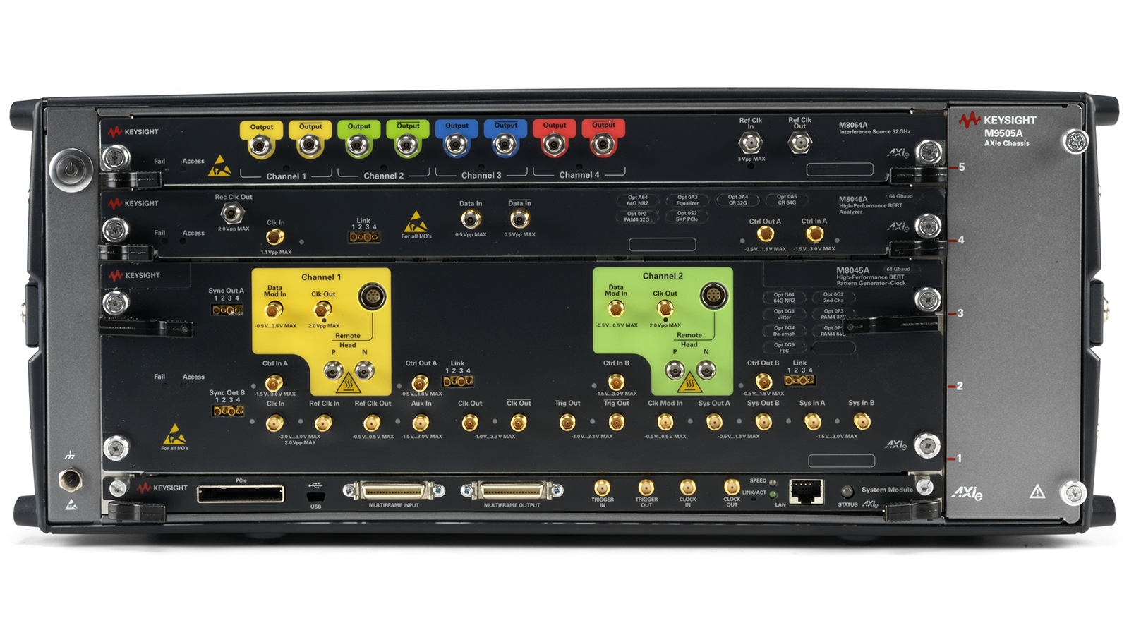
Keysight’s bit error ratio test (BERT) system enables the most accurate physical-layer design verification of high-speed communication and multi-gigabit digital interfaces. Our expert-level support will help you select the high-performance hardware, control software, receiver test, and automation tools needed to help you master your design.

Whether you are working on data center or computing interface technologies, Keysight BERTs offer the most comprehensive choices, from affordable manufacturing test to high-performance characterization and compliance test.

The Keysight BERT supports symbol rates up to 64 Gbaud with both non-return-to-zero and pulse amplitude modulation 4 (PAM4) coding schemes. It also supports digital interfaces such as PCI Express®, USB, MIPI, Thunderbolt, DisplayPort, SATA / SAS, electrical and optical Ethernet 10G / 100G / 400G, OIF-CEI, Fibre Channel, and PON.

Extend Your Capabilities With The Right Tools

Technology is constantly changing. So too are the requirements engineers face. Get more functionality out of your existing hardware today by complementing it with the right accessories to improve productivity and the right Keysight PathWave design and test automation software to accelerate your product development.

Related Use Cases

How to Validate Optical Transceiver in MRI System

How to Validate Optical Transceiver in MRI System

Validating optical transceiver performance in MRI systems requires testing the components to ensure effective functionality in high magnetic strength environments. Learn how to use a sampling scope and jitter bit error ratio tester to verify optical transceiver compliance.
How to Characterize and Test DDR5 Receiver Compliance

How to Characterize and Test DDR5 Receiver Compliance

Test DDR5 receiver compliance with precision. Ensure high performance and accuracy in DDR5 designs. Learn more on Keysight's official page!
How to Optimize 800G Optical Transceiver Manufacturing Tests

How to Optimize 800G Optical Transceiver Manufacturing Tests

Manufacturing testing optical data center transceivers requires efficient analysis of TDECQ measurements. Learn how parallel data acquisition and analysis increases throughput to save cost of high-volume testing.
How to Test USB4 Version 2.0 Receiver Compliance

How to Test USB4 Version 2.0 Receiver Compliance

USB4 Version 2.0 receiver testing requires precise stress signal calibration, consistently repeatable pattern generation, and bit error rate measurements. Learn how to perform a USB4 Version 2.0 receiver compliance test using a bit error ratio tester (BERT), a high-bandwidth oscilloscope, USB receiver test application software, and the USB-IF SigTest utility.
How to Perform DDR5 System Validation

How to Perform DDR5 System Validation

Validating DDR5 devices and systems requires protocol layer testing with a logic analyzer and analysis software. Learn how to perform DDR5 protocol layer analysis and validate your DDR5 system using a logic analyzer, memory analysis software, and probes with BGA interposers.
How to Test and Debug DDR4 Systems

How to Test and Debug DDR4 Systems

Engineers implementing DDR4 systems and memory require a solution that provides trace capture and analysis, enabling insights needed to understand system behavior. Learn how to test your DDR4 memory system’s performance and protocol functionality analysis for complete compliance.
How to Analyze PAM4 Receiver Signals

How to Analyze PAM4 Receiver Signals

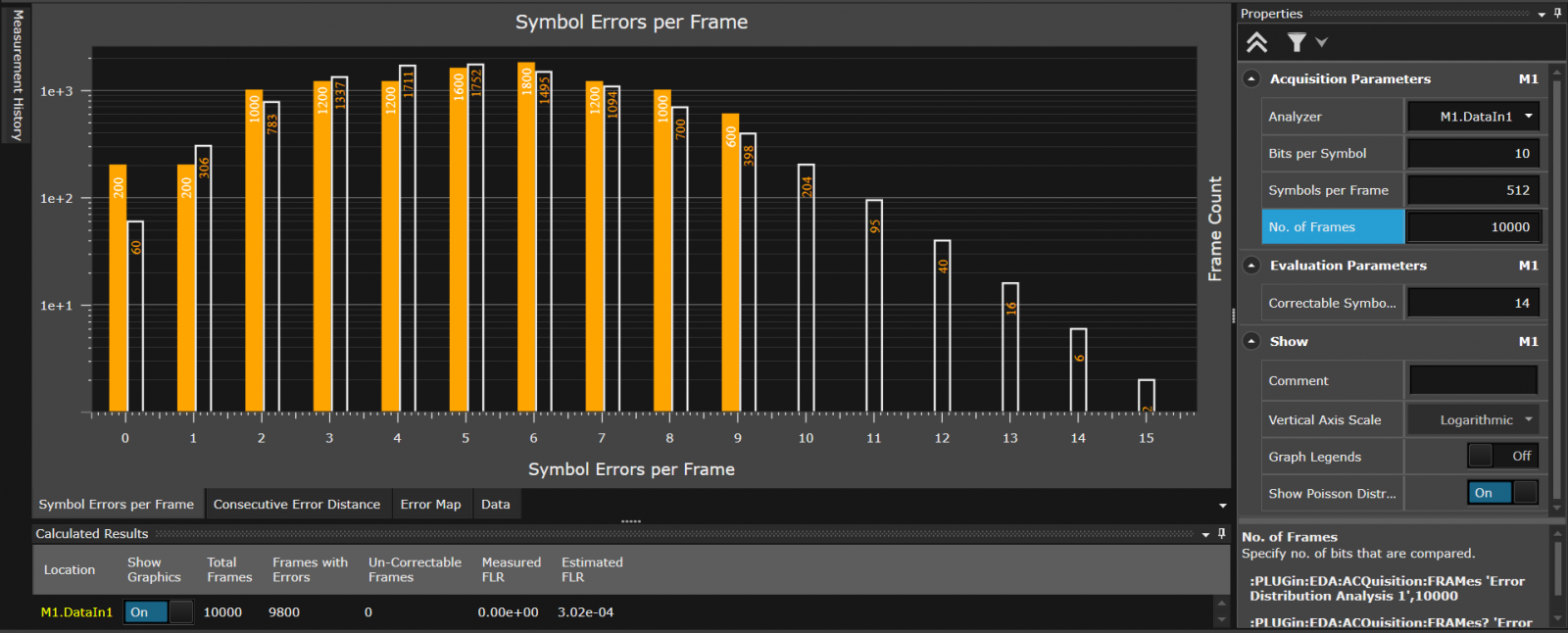
Analyzing PAM4 signals requires multiple-bit error rate (BER) and symbol error rate (SER) measurements. Learn how to characterize a PAM4 signal at the receiver fully.
How to Test 400G / 800G Electrical Receiver Conformance

How to Test 400G / 800G Electrical Receiver Conformance

Conformance testing for electrical Ethernet links require bit error rate and forward error correction testing using a bit error ratio tester and high-bandwidth oscilloscopes. Learn how to prove receiver interoperability and conformance to IEEE and OIF specifications at 53 GBd PAM4 signaling using receiver compliance test tools to automate the process.
How to Test PCIe® 5.0 Receiver Compliance

How to Test PCIe® 5.0 Receiver Compliance

Verifying Peripheral Component Interconnect Express (PCIe) receiver compliance involves testing the PCIe® 5.0 device's receiver performance with a bit error ratio tester. Learn how to calibrate your stress signal and test for PCIe 5.0 receiver compliance with automated test tools.
How to Test PCIe® 6.0 Receiver Compliance

How to Test PCIe® 6.0 Receiver Compliance

Testing PCI-SIG devices requires robust receiver compliance validation to certify PCIe® 6.0 device interoperability at 64 GT/s with PAM4 signals. Learn how to calibrate your stress signal and test for PCIe 5.0 receiver compliance with automated test tools.
How to Test USB4 Receiver Compliance

How to Test USB4 Receiver Compliance

Testing physical layer (PHY) USB4 electrical performance requires executing conformance tests defined by the Universal Serial Bus Implementers Forum (USB-IF). Learn how to tune and calibrate a bit error ratio tester's (BERT) stress signal amplitude, channel equalization, and insertion loss to achieve accurate stress conditions required for conformance testing.

Featured Resources

View All Resources

View All Resources

Frequently Asked Questions - Bit Error Ratio Testers (BERT)

The basic concept behind the bit error ratio test (BERT) is straightforward. A BERT compares the errors received in the data stream through the communications channel, with the originally sent data stream. The resulting bit error ratio (BER) indicates the number of errors introduced by the transmission channel. BER is the number of bit errors divided by the total number of bits sent. Bit error testing validates the performance of communications data links.

A bit error ratio tester, or BERT, compares the ratio of the bit errors received to the total number of bits in the transmitted data stream. Bit errors arise from noise, distortion, failed bit synchronizations, and other transmission anomalies.

The bit error ratio is the ratio of the number of bit errors received to the number of total bits sent. A BERT compares the transmitted sequence of bits to the received bits and counts the number of errors. Therefore, BERT stands for bit error ratio test but is more commonly referred to as bit error rate test.

Want help or have questions?